My robot lapped my kitchen on its own. Here’s what changed.
Four complete laps around a blue-tape oval on my kitchen floor, then seven after a reset — by my count at the truck. Each streak ended in a crash on the corner exit. After three nights of tuning, an outside review found errors in the camera-to-steering pipeline. Three repairs went in before the laps, so I still haven’t isolated which made the difference. The later baseline showed the remaining gap: counterclockwise laps worked; clockwise, the truck repeatedly missed the tight corner.
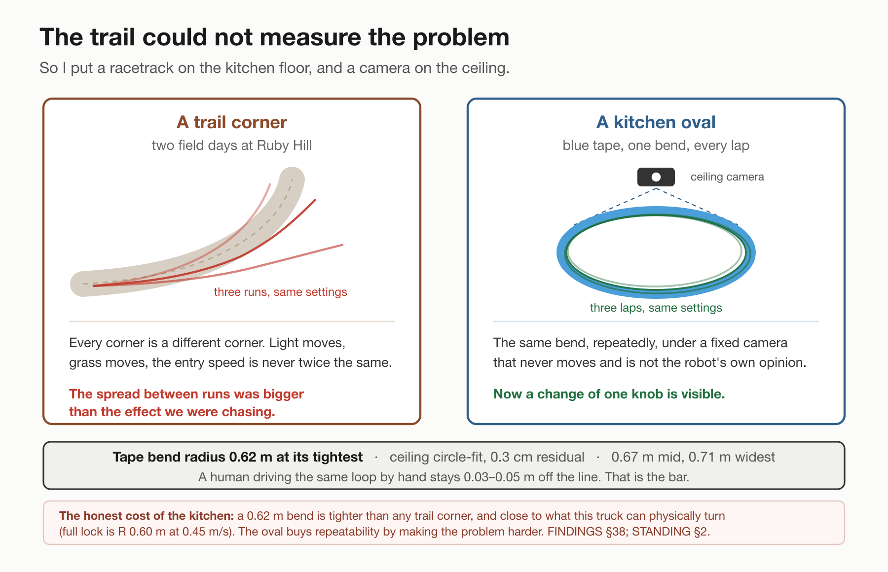
Last time this was a truck on a trail that could hold a straight and could not hold a corner. Over two field days I tried lookahead distances from one to three metres — how far up the path the controller aimed — and steering gains from 1.0 to 2.1. None of the settings we tested made the bend reliably, and the variation between passes made them hard to compare. This time it is the same truck driving an oval of blue tape on my kitchen floor, about 4 m by 1.7 m, with a camera fixed above the bend watching it.
The vision model kept the same architecture: a frozen backbone [1] and a 385-number head that scores the tape in each image. I retrained that head on my hand-driven kitchen laps, using labels projected from where the truck actually drove.
A separate steering controller sits between those tape predictions and the servo. It fits a line through the predictions, selects a point ahead on that line, and calculates how sharply to turn. Confidence checks, gain and steering limits shape the request; the flight controller sends it to the steering servo. I can take control with the wheel.
I changed how I tested and measured that system: a repeatable track, a way to keep driving through resets, and a fixed camera watching the bend. Later in the session, I also repaired the timing and coordinate calculations in the camera-to-steering pipeline. Those are different changes, and this log follows what each one could tell me.
1 · What changed since last time
The truck is unchanged: Jetson Orin Nano Super in a printed cradle, Pixhawk flight controller running ArduRover, an iPhone on a wedge mount looking forward over the hood of the truck, and one USB cable carrying video from the phone to the Orin. Log #1's obstacle model is not in this post at all; nothing here is about not hitting things. What is new is around the truck — 24 mm blue tape on the kitchen floor, a machine-vision camera on the ceiling over the bend, and a way of driving where I keep the throttle on my trigger finger and take the steering back the instant I touch the wheel.
One repair on the night I laid the tape, 2026-09-08, because it explains a number later on. Hand-driving the oval at a crawl, the steering kept sticking — stuck in whatever position it was in, about three seconds, released when I stopped. A fresh pack changed nothing. Earlier that evening I had moved the flight controller's steering centre from 1500 µs to 1463 to match the truck's real straight, which left the servo 437 µs of travel on one side and 363 on the other, so one side could be driven past the steering linkage's mechanical stop. Pulling the other endpoint in to match made it 363/363. Stops of 0.6 s or longer went from 11 in 193 seconds to 3 in 140 — but those are two hand-driven runs of different lengths on one evening, not a controlled comparison, and I drove the second one faster (median 0.37 → 0.45 m/s) into exactly the speed range the suspected cause is least bad at. It was one cause, not the cause — I pushed back on that the same night, and the log's own freeze list holds servo values at both endpoints and at dead centre. The explanation for the rest — the servo browning out a power supply rated for a third of what it draws when stalled — has never been instrumented, and the standalone supply that would fix it still isn't fitted.
A word on how this work gets done, because it is part of the record. I design the tests, drive the truck, and call every result before the grade comes back. Coding agents write the tooling and do the analysis — the matrices, the regrades, the replays — at a volume no one person could. What I bring is the method: one knob at a time, every run logged, every number traced, and the habit of asking whether a tool's output is a fact about the world. Four of the five catches from these nights were mine; the fifth was an outside review, which found two defects in one evening and the logging stall in a second round. For scale: the controller has 43 tunable parameters (102 flags in all). Six of the ideas behind them come from papers; the other thirty-seven flags are the gates, guards and plumbing it takes to run six ideas on a real truck with a phone for eyes. In this log, one constant demonstrably changed the steering requests in an offline replay; whether that change explains the laps remains untested. The rest of this post is about finding out which.
2 · The test setup: a racetrack on the floor, a camera on the ceiling
2.1 · The finding that earned the tape
The reason I could not tune the corner outdoors is the finding from Log #2, and it is worth restating because everything here follows from it: run-to-run noise was larger than the effect I was measuring. The throttle was my trigger finger, so no two passes entered the bend at the same speed or on the same line, and with one pass per setting I could not rank two lookaheads half a metre apart under that spread.
So I built something that repeats. Blue tape, kitchen floor, one evening.
One retained 13.9-minute baseline log contains 14 separate forward entries into the near-bend region, with model steering selected at entry. That elapsed time includes waits and resets. Some attempts later needed help; this is a count of encounters with the bend, not a success grade. The counting method and its limits are below.
How much sharper it is, stated carefully: my own hand-driven laps of the oval on 2026-09-08 repeat to 0.028–0.031 m RMS lap to lap by the phone’s own track, against 0.62 m of dispersion at the Ruby Hill corner. (A coincidence of digits: the bend radius in the next section is also 0.62 m. They are unrelated quantities.) Those are not the same statistic — one is the scatter of my own laps around their own mean on a taped course, the other is the spread of where the truck ended up across passes at a trail corner — so there is no ratio to read. The point stands either way: outdoors, the reference line was less repeatable than the error I was chasing.
2.2 · The camera on the ceiling
I needed a view of the truck’s motion separate from its own camera predictions. On the trail that was a tripod on the bank. Indoors it is a machine-vision camera at the ceiling, roughly 2–3 feet off the centre of the loop and about 15° from vertical, looking down at the bend (Figure 2). It traces the tape, fits the loop, and reports how far off the tape the truck was, frame by frame. Its initial scale came from the 24 mm tape width. That single scale proved inadequate across the tilted view; the calibration limitations are part of every grade below. Camera and recording details are listed below.
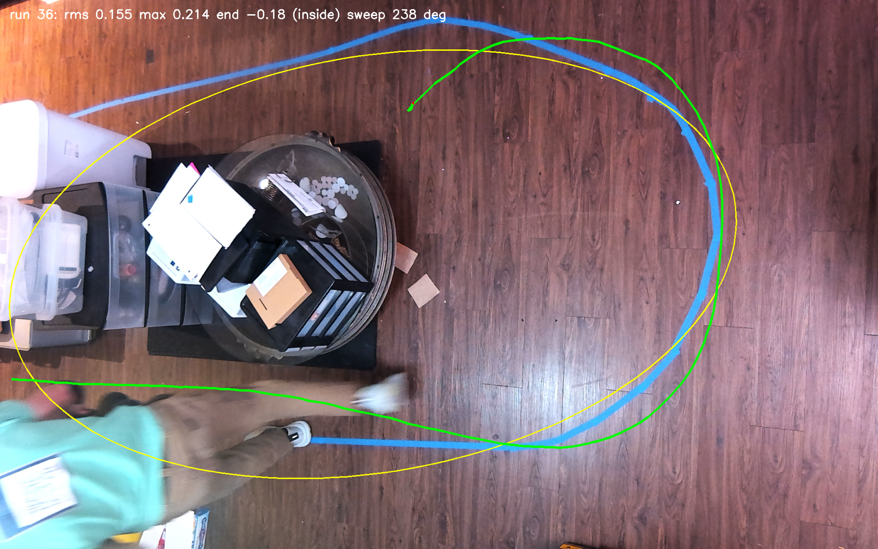
It took most of a day to make that camera trustworthy — rebuilt four times in one evening and usable for the reported bend grades from 21:40 on 2026-09-10, not before; its metre was corrected twice — and separately, a single 45-minute recording holding six cells lost its index when a restart killed it, so those cells have log statistics and no video — and it never once graded a whole lap: its run splitter closes a run at the first lost frame, so every number it produced is per-fragment, and where a lap is the unit the phone's own track is the referee instead. Two things I got wrong with it later and should say here: its calibration was up to 0.48 m wrong on the left third of the loop, and there is no single scale — twelve hand-measured tape spans give 382 to 647 pixels per metre across the floor, because the camera is well off vertical. The full list of what went wrong with it is in the troubleshooting guide.
2.3 · What the oval costs
Three costs, and none of them is small.
The first is that the bend is tight. The tightest end is 0.62 m by a circle fit to the ceiling camera's trace of the tape, and 0.65–0.82 m by four sessions of the phone's own motion tracking — two instruments, quoted separately on purpose. Full lock on this truck is 0.60 m at 0.45 m/s, measured from 249 quasi-steady samples of the flight controller's own servo output against the path curvature the phone recorded. The bend and the truck's minimum radius sit inside each other's error bars — 0.62 m against 0.60 m — so "at the lock limit" is not a claim I can make in either direction. It is tighter than anything on the trail.
The second is that I had it written down wrong. For the first two nights this oval was a "1.3 m radius" course in my notes — off by a factor of two — and every conclusion drawn about how much steering the bend needed was scaled by that error. It was corrected from the recorded pose, not from a tape measure, and the correction is the reason the rest of this post is about the fitter and the pipeline instead of about gain.
The third is that the steering head I had trained outdoors is no use in here. It was trained on trail, at trail speed, on a course whose curvature never approaches this; run on kitchen frames its column error is about four patches and it asks for roughly a third of the turn the tape needs — it still tracks the line, weakly, but not well enough to steer on. The head that drove everything in this post was retrained from twenty of my own hand-driven oval laps — 207 metres, 2,838 frames — in about two minutes on a laptop. (Retrained, not fine-tuned: the backbone never changes, and the 385-number head is fitted from scratch each time.)
3 · Three nights of turning one knob at a time
3.1 · What a cell is
The method is an eye test.
An optometrist does not ask you how blurry your vision is. You could not answer. They change exactly one lens and ask which is better, one or two — because a comparison between two things you have just seen is something a person can actually deliver, and an absolute judgement is not. So: a cell is one setting of the truck, held fixed, driven two or three times, with the same person driving the resets and the same referee grading — the phone's own track on the first night, the camera on the ceiling from the second. I call the cell from the end of the straight, in a sentence, before the grade comes back. Then one knob moves, and only one, and the next cell runs.
The evening of 2026-09-09 was 45 runs. The following day was nine hours at the truck: sixteen labelled settings, 80 graded runs under the model and fifteen laps of my own hands as the reference — counts from the matrix's own run table, re-read for this post. My sentence and the pose grader's number agreed on every cell of the first night, which is the only reason I trust either of them.
Changing one factor at a time can miss interactions [2]. The patterns in this matrix suggested that corner entry and exit could respond differently to cap and gain, but the partly-crossed trials and varying speeds did not isolate those effects. That is a hypothesis for a controlled comparison, with speed held steady. I also nearly ran my whole first night on one side of the failure before asking why nothing overshot; the rule I wrote afterwards — the first cell after any diagnosis is the one that should fail the other way — is seventy-eight years old and has a paper [3].
(The eye-test analogy stops at the lens. An optometrist's lenses don't interact; mine do, completely. The tool computes steer = gain × curvature ÷ full-lock-curvature, so the gain and the full-lock constant are the same knob wearing two hats — when I corrected full lock from 1.43 to 1.66 1/m, that was arithmetically identical to lowering every gain I had ever measured by about 14 %. And an optometrist's patient does not change between lenses. Mine does: the battery sags, and the same throttle number that crawls at 0.2 m/s on a tired pack runs 0.45 on a fresh one.)
3.2 · What three nights of cells actually found
One cell was better than the others. On 2026-09-10 at about 23:15, after nine hours, G2 — lookahead 0.8 m, gain 1.5, curvature cap 1.5 1/m, fit window 0.8 m, cruise 1650 µs — became the first setting in two days to complete the tight bend on the tape with the tape in view.
Nine graded runs: mean maximum cross-track 0.223 m, one of nine lost the tape, ending 0.04 m off the line on average, 158° of arc, at 0.45 m/s. One caveat travels with that, attached: these are a handful of runs inside one evening on one course, not a controlled comparison against anything.
The ladder around it, same evening, speeds not held: gain 1.0 lost the tape in six of eight runs at a median moving speed of 0.36 m/s; 1.3 in three of seven at 0.38 m/s; 1.5 in one of eleven at 0.48 m/s. The nine-run G2 summary above excludes two runs shorter than three seconds from those eleven. Gain 1.5 was also the fastest cell by 0.10–0.12 m/s, so this ladder ranks gain and speed together, not gain.
And underneath it, the finding that does not fit on a knob: with gain at 1.0, every curvature cap I tried — 1.0, 1.25, 1.5, 2.0 — and both fit windows ran 0.23 to 0.45 m wide on the way out of the bend and lost the tape there. Zero of twenty-three runs ended on or inside the line. Gain 1.3 brought three of seven back. Gain 1.5 capped the swing at 0.22 m. Entry and exit changed across these trials, but cap, gain and speed were not isolated well enough to assign each effect to one setting.
One more thing about that evening, because it is the most instructive failure in the whole post and it has nothing to do with software. Earlier cells had been ending inside the line, which looked like a real and rather encouraging result. Then I moved a round table out of the corner, and every cell after that completed the arc and a wide exit appeared. The table base had been stopping the truck at 119–135° of sweep, and I had been reading that as an ending. The best cell of the early evening is an artefact of a piece of furniture.
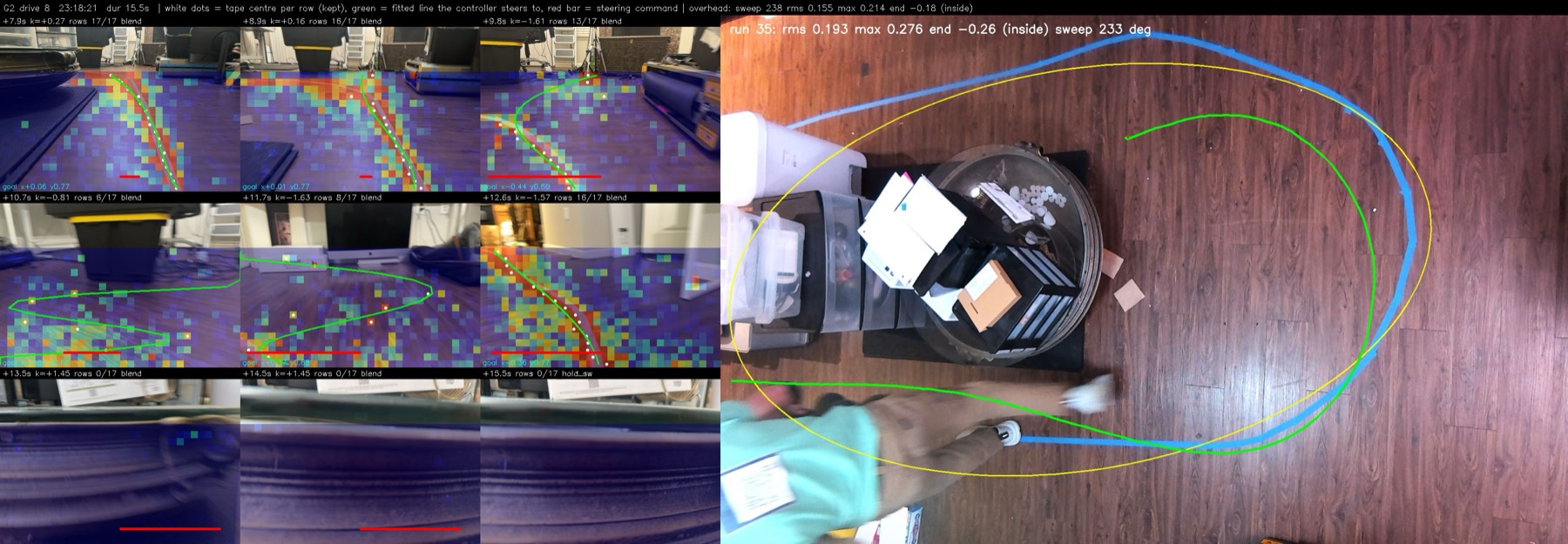
How to read the sheet
| Location / mark | Meaning |
|---|---|
| Left, nine camera panels | Recorded on-board images with model-output overlays. The coloured grid is per-patch tape probability; white dots are the retained per-row tape centres. Neither is independent ground truth. |
Left, green curves and cyan goal labels |
The sheet's drawn fit and selected goal coordinates. The conspicuous loop at +10.7 s is interpolation by the sheet script, not the line used by the controller. |
Left, red bars and k labels |
Steering request and logged commanded curvature, not a measured wheel angle or vehicle path. rows counts retained rows, which can exceed the rows voting in the fit. |
| Right, overhead panel | Blue is the physical tape; yellow is the grader's fitted loop; green is its tracked vehicle path. These are external observations/estimates, with the calibration limits described in §2.2. |
The later log replay found the command-changing event between the +9.8 and +10.7 s panels, at +10.53 s: a straight-line fit used six voting rows despite retaining eleven. The logged request weakened from −1.657 to −0.872 1/m; flight-controller servo-output telemetry then changed from 1825 to 1642 µs. At +11.7 s, the goal changed sign, but the minimum-row gate held the previous request. The dramatic drawn loop is not evidence that the truck obeyed a looping cubic.
The overhead panel is not a verified paired outcome for these frames. Its embedded label says run 35 (233° sweep, 0.276 m maximum deviation), while the sheet header quotes run 36's values (238°, 0.214 m). I retain it as part of the historical diagnostic sheet, not as synchronized proof of drive 8's motion or a completed lap. Figure provenance and replay references.
3.3 · The day five settings changed the behaviour and improved nothing
On 2026-09-12 I drove five control cells between 10:50 and 16:00, one knob each, every deployment byte-verified, every flag read back off the running process. Lookahead 1.2 with gain 1.5. The same with one hold disabled. Lookahead 0.7 with gain 1.3. The same again with the mount angle read live per frame. Then the curvature cap loosened from 1.5 to 3.45.
The historical regrades put the first cell at or near the front, but the five-cell comparison does not establish which setting was best: speeds were not held, and the ceiling calibration was faulty. The cells changed the behaviour without establishing an improvement.
I am leaving out the five per-cell medians. The regrade that produced them was a throwaway script that never got committed, and the raw grader output gives different values. Speeds were not held or ledgered per cell, and the camera's calibration was up to 0.48 m wrong on the left third of the loop. Before I can quote those numbers or rank those settings, the comparison needs a reproducible regrade with those limitations attached.
Twice that day I asked whether the line fitting was improving, and twice the answer was no, it has not been touched. Both times I was the one who asked, and both times the plan carried on anyway, because the written plan was concrete and the question was short. Somewhere between one day's notes and the next, "change one line-fit knob" had become "change the lookahead", and the lookahead is not a line-fit knob. Two and a half hours went to executing the written words.
And the best two runs of the first matrix night were sitting in the record with no number attached to them — graded 0.042 and 0.037 m by the phone's own track, a different instrument from the ceiling camera above and not comparable to it, at that instrument's noise floor. My notes carried one trace of it: a parenthesis reading "(gain 1.3 was tried 09-10)". "Was tried" reads as "was ruled out." So the day moved the lookahead further away from 0.7, to 1.2.
4 · Three numbers my tooling got wrong and I repeated, and one run that wasn't a run
This is the section the post exists for, and I'd rather write it than the one about the laps.
Start with the run that wasn't a run. On the evening of 2026-09-11 I drove five laps of the oval with the truck armed, the model running, the log recording, and reported them as the evening's result. They graded beautifully — entry, apex and exit at 0.065, 0.049 and 0.070 m, none lost. Later that evening I pulled the Orin's own log. On all 3,504 frames the knob that sets how much of the steering comes from the model was at its minimum, weight zero; the difference between what the model asked for and what my own wheel was doing had a median of exactly 0.000. I had driven all five laps by radio myself. The model's command was computed and written to disk every frame and never sent to the servo; the only thing the tool contributed was the throttle. The rule that came out of it is that a run only counts if the first frames of it say so in the log, and that checking the flags is not checking the deploy. (The twist that matters: the state the log printed does not decide who is steering — the knob does. The very next night the model did steer with the switch in the same middle position, and the servo followed the model's command at a correlation of 0.95–0.99.)
Then three numbers — all produced by my tooling, all repeated by me as measured fact, and all three caught by me the same day.
One. "The model is driving" was the wrong definition. I defined it as the frames where cruise control was engaged. But the whole point of keep-going mode is that I hold the throttle on my trigger, and a human trigger pull vetoes cruise. So that filter selected 131 frames out of 4,643 — under 3 % — and everything downstream of it was junk computed correctly. It produced a phone mount that had "drooped to 9.7°" (9.7 was the minimum of one run; while the model was actually steering it sat at 13.8–15.1° all day). It produced per-cell grades that inverted when regraded. It produced a steering bias that turned out to be the steering law correctly chasing a goal 2.5 cm off centre. I re-seated the phone for nothing, and I loosened a real safety limit on the strength of it — a limit I then had to put back, because the loosened version drove worse.
Two. I read a noise peak as a turning radius. A tool that reports the maximum curvature along a recorded path is not reporting the radius of the bend; it is reporting its own worst single sample. Read as a radius it said 0.46 m, and from that I said the truck physically could not make the tight bend. Circle fits say 0.62–0.63 m against a 0.60 m lock. This was the fourth time in this project that the tooling had announced the truck cannot make the turn, and the fourth time I overruled it from the floor. It makes the turn. It has for days, by hand. Every single time that claim has been made, the real cause was upstream of the wheels: a declared-wrong mount angle, a lookahead longer than the fit window, a grader capped below the thing it was measuring, a calibration half a metre out, a filter selecting 3 % of the frames.
Three. I read the ceiling camera's search limit as a result. It searches 0.45 m either side of the tape; nothing it reports can exceed 0.42 m; and 18 of 31 passes sat exactly at that wall. I quoted those as excursions.
All three have the same shape, and so does the run I drove myself: a definition, or a tool's own output, taken as a fact about the world, and then defended with perfectly correct arithmetic on top of it. The arithmetic was never wrong. The thing being measured was never re-checked. Nothing in my loop ever asked the one question that separates a proxy from the thing it stands for — what fraction of the run does this filter actually select? — which would have shown 131 of 4,643 in one line.
5 · So I asked someone else
At about half past four on the afternoon of 2026-09-12, after five cells that changed the behaviour and improved nothing, I stopped and sent the actual source and the actual logs out for an outside review. (An AI code reviewer, not one I had used on this project. I'm recording that because the process is part of the record; the findings below were each verified against our own logs before they went anywhere near this post, and one of them contradicted a number I had recorded the day before.)
It came back with two defects in a few hours. Both were real. Neither was a setting.
5.1 · Half a second blind
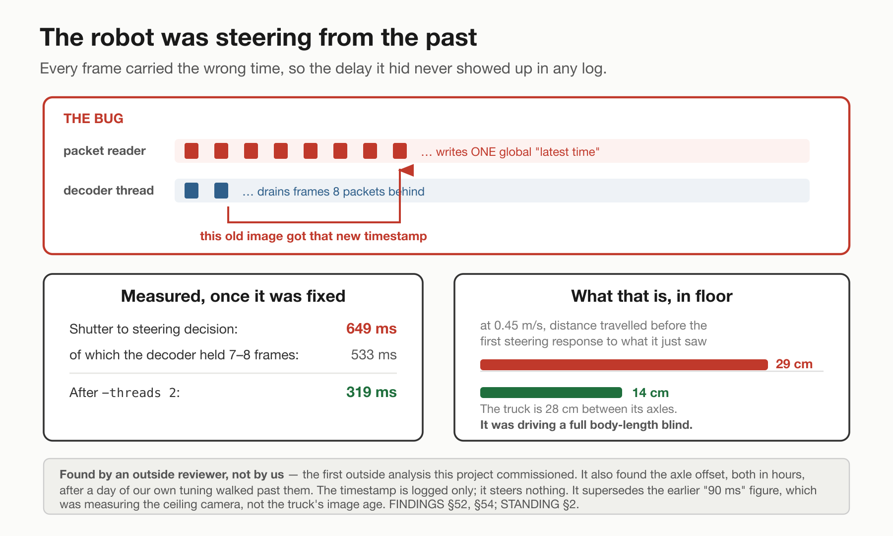
The image the steering model was looking at was 533 milliseconds behind the newest packet and 649 milliseconds behind the moment the light hit the lens (Figure 4). At 0.45 m/s that is 29 centimetres of travel before the truck can react to anything at all, on a course whose bend has a 0.62 m radius.
The cause is ordinary and documented and I should have known it: ffmpeg's default is frame-threading across the available cores, and a decoded frame only comes out when the thread pipeline is full. The decoder was holding a steady seven frames, about 533 ms of them. Setting it to two threads took the held depth from seven to two and capture-to-record from 649 ms to 319. Fourteen centimetres instead of twenty-nine.
None of that is new. Video engineers have known about frame-threading latency for over a decade and the remedy is a documented flag. Distance blind is delay times speed; the only thing particular to this truck is that the delay was inside the decoder rather than anywhere I had thought to look.
The truck in this post drove at 317–322 ms. The later latency work belongs to a separate experiment.
5.2 · The steering was measured from the wrong end of the truck
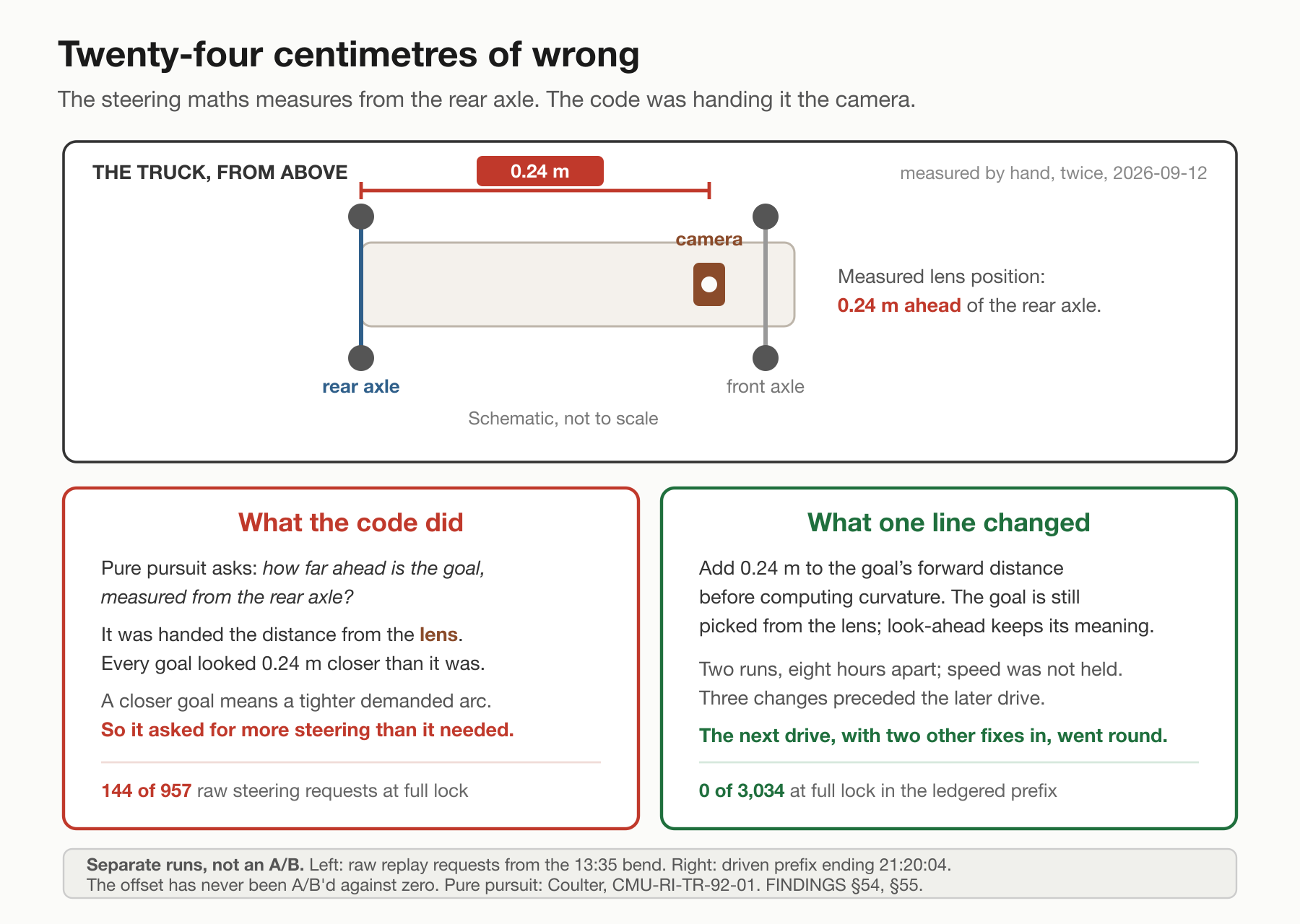
This is the hero of the post and it is one number in one flag (Figure 5).
Pure pursuit picks a goal on the path a fixed distance ahead and computes the curvature of the arc that reaches it. The curvature is two times the goal's sideways offset divided by the distance squared — and Coulter's 1992 description of the algorithm [4] is explicit that the vehicle's coordinate system belongs at the centre of the rear axle, citing a reason: with the origin there, steering and propulsion are geometrically decoupled. My code was handing it a distance measured from the camera lens, which on this truck is 0.24 m forward of the rear axle — measured by hand, twice.
So every goal looked closer than it was, and because of the inverse square, a goal that looks closer produces a much harder steering request. Replayed offline on a failed bend from earlier the same day — 957 frames, model steering, nothing gated — adding the offset took the raw steering requests that were at full lock from 144 to 0, and halved the median command from 0.60 to 0.33 1/m. The goal's distance went from a median of 0.67 m at the lens to 0.91 m at the axle.
Again: known, and worth citing rather than claiming. Qin and Li (2022) [5] describe exactly this — a bicycle model written for the rear axle, applied at another point on the car — and note that the resulting sway on curves "has been previously misunderstood as improper choices of control parameters." That is a published description of the three nights I had just spent. In a normal robotics stack the path reaches the steering law already transformed into the robot's own base frame [6], so where that origin sits is a decision someone made on purpose. I had a function that returned metres.
6 · Four laps, then seven
At 21:13 on 2026-09-12, with the offset in and the pipeline at 319 ms, same head, same tape, same knobs as a cell that had been cutting the corner that afternoon, the truck went round the loop on its own.
I counted four complete consecutive laps before a corner-exit crash. After resetting the truck, I counted seven before another exit crash. The longest hands-off stretch in the log is 63.5 seconds. What I said at the truck, and it is on the recording, was "it's made it around 5 times now" and then "holding the line through the corner really well, it wanders … that one was like seven times."
The steering log offers a narrower result than the lap count: none of the 3,034 model-steering moving frames in the ledgered prefix ending at 21:20:04 asked for full lock. Median command was 0.60 1/m and maximum 1.58, against full lock of 1.66. The afternoon's 144 of 957 figure counts raw requests in an offline replay of a different run, before smoothing. These are different populations, eight hours apart, not a controlled A/B; the whole-run denominator is still unresolved.
When a controller asks for more steering than the actuator can deliver, further increases in the request cannot produce more turn. The feedback loop still exists, but the actuator is at its limit. In the offline replay, adding the axle offset removed saturation from the tested requests. I am not claiming the offset is why it lapped — that comparison was never run. The run before and the run after are different runs, eight hours apart on the same day, on different packs, at no matched speed, and three changes went in between them: the timestamp fix, the decoder threads, and the offset.
These were the two crashes that ended the lap streaks. In each, the truck made the corner entry, then stopped turning halfway to three-quarters of the way around the bend and ran off on the exit — the second time into a garbage pail. The crash reports do not establish a direction switch between the streaks. The clear comparison of counterclockwise and clockwise came later, on the fixed build.
Two more single changes that half hour — the row gate loosened and kept on the evidence against my own verdict at the truck, the curvature cap loosened and rejected after four laps — are in the notes; neither is the story.
Then the outside review's second round found something that had been sitting underneath every long run of the night. Every 500 frames, the tool re-compressed its entire probability history inside the control loop. The loop interval on those frames grows as the history grows: 102 ms at frame 500, 707 ms at frame 7,000, and past about frame 5,000 it exceeds the steering forwarder's 500 ms watchdog — which substitutes zero steering (Figure 6). Frames 7,000–7,001 of run auto-boot-215204 show it exactly: the held command sits unchanged at −1.60, and the steering output goes from −0.96 to 0.0 and the servo from 1811 µs to dead centre, at 0.56 m/s. Every run longer than about five and a half minutes that night had its steering centred for a beat every 33 seconds, on top of whatever that cell was testing. The per-frame timing statistic the tool printed excluded the checkpoint, so it never showed.
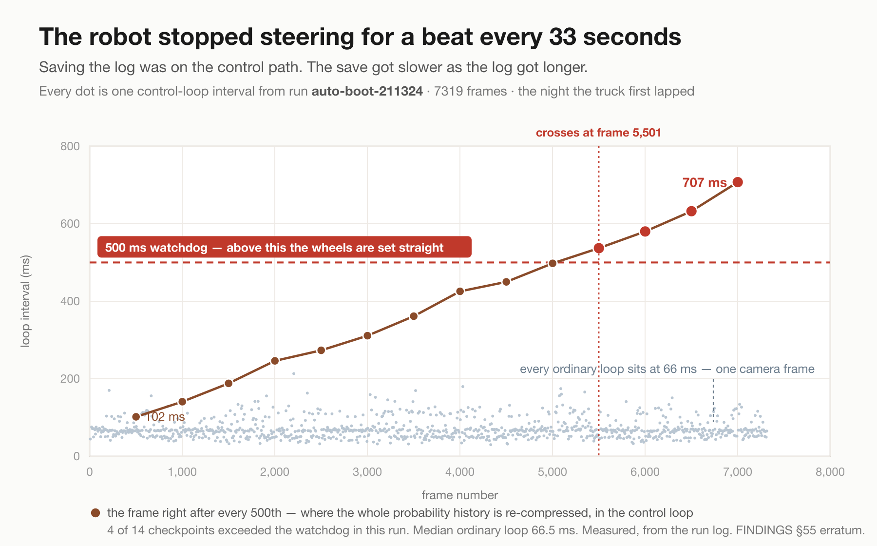
It was fixed and benched the same night: 8,239 frames stationary, checkpoint intervals down to 44–144 ms, no interval over 500 ms after startup. At 23:42 I drove the first honest baseline — one configuration, both directions, matched speed, on the fixed build. Counter-clockwise: every corner made, seven laps, visibly less wandering than before, sitting a little inside the tape after each corner and then rejoining. Clockwise: the far corner made, and the near, tightest corner missed every single time, at cruise and slowed.
What I could see from the floor was the thing the log did not have. That near corner is not one corner. It is a turn, a short straight, and then a turn again — a compound corner. My reading was that, on the short straight, the camera was already seeing the second bend: the truck turned early, straightened, and reached the real bend with too little room. That was the observed failure of this camera fit and fixed 0.7 m lookahead. It did not establish an inherent inability of pure pursuit to follow a compound corner, or isolate which fit or goal-support error caused the miss.
That turns out to be a published rule with a number in it. Park, Deyst and How's 2004 guidance paper [7] — a close relative of the same steering law — states that the lookahead must be less than about a quarter of the shortest wavelength in the path. At 0.7 m that demands a turn–straight–turn cycle longer than about 3 m of arc. I have never measured that end of the oval as its own arc, so I cannot establish that this criterion explains the miss. It suggested a shorter-lookahead experiment. I took it to 0.6 m as the one cell of the night. It was a split: the entry of the compound corner went from never to sometimes, and the exit did not move at all. I kept it, unproven.
The exit failure is now described precisely enough to test, and my own description of it is the most useful thing I have: the last 15 % it all of a sudden stops turning, and the tape is between its tyres.
7 · The wall is not a knob
The wall is not a knob, and it took me three nights of cells to see that as the finding rather than as a bad night.
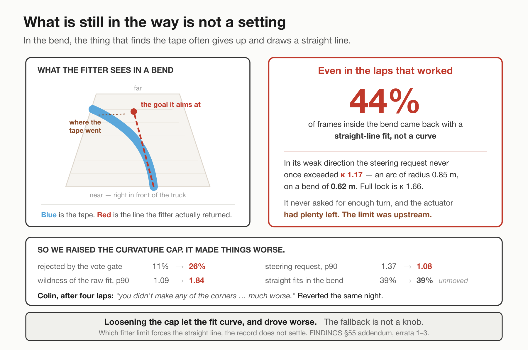
Gain cannot restore path geometry discarded by the fit. A straight fitted line can still supply an offset goal, and pure pursuit will command curvature toward that goal. The problem is whether that goal represents the bend the truck needs to follow. In the counter-clockwise laps with curvature cap 1.5 and min-rows 10, 44 % of the frames inside the bend carried a straight-line fit (Figure 7). Which of the fitter's limits forced that, my own notes disagree about, so I'll give only what was measured: in its weak direction the request never exceeded 1.17 1/m against a bend that needs about 1.6 and a lock of 1.66. Loosening the ground-frame cap did let the fit curve, and drove worse, so the fallback is not a knob either. It is a reason to stop asking the camera alone.
There was an earlier warning I should have followed up. At 00:25 on September 12, after a set of straights I called the worst testing we had had in days, I asked for a comparison with the better straight-line runs from two nights earlier. Work continued, but that specific comparison was not carried out until September 20. It identified two changes worth investigating: a gate-and-hold rule deployed on September 11 that held or locked a fifth of the straight-line frames, and a fit that placed the goal about five centimetres left of the camera’s axis while the truck sat on the tape. The sequence matched what I had described from the floor — veering left every single time and then going right. I should have compared the running configurations and those recorded signals before trying more settings.
No tested gain resolved both the approach and the bend: turn it up and the truck hunted side to side on the approach; turn it down and it ran wide. Pure pursuit can follow a curved path: with the rear axle on a circle of radius R and the vehicle aligned with its tangent, a correct goal on that circle makes 2x / (x² + y²) request curvature of magnitude 1/R, with the sign set by the turn direction. My steering request depended on the goal supplied by the camera fit. Getting a useful goal through that clockwise corner, consistently, was still unresolved.
By the end of the September 12 session, running just past midnight, I had a real success: counterclockwise, the truck was making every corner. I had counted seven consecutive laps in the fixed-build baseline. Clockwise was still inconsistent. Shortening the lookahead had helped it enter the tight corner sometimes, but it still failed on the exit.
That is where this episode ends. I could get it around one way; the next goal was to get it around the other way consistently, too.
Next: can I get it lapping reliably in both directions?
8 · What I learned, and what I want to test next
The laps were real progress. They also showed how easily I could spend an evening tuning around an error in the information reaching the controller. Image age, the point from which a goal is measured, and pauses inside the control loop all changed the steering request or when it reached the wheels. A better-looking run did not identify which repair helped it.
What I would do differently: before another tuning matrix, I would check the frame’s age, the rear-axle coordinate calculation and the complete loop timing, including recording work. I would also verify steering travel and repeat a baseline at matched speeds. The overhead camera needs calibration across the floor and a recording that survives resets; a clipped corner fragment cannot grade a complete lap.
What I think I learned: the fit and its selected goal deserve as much attention as gain. Straight-line fallbacks and held commands were recorded, and the clockwise exit still failed. That makes them useful candidates to inspect; it does not establish which one caused the miss, or a general limit of pure pursuit.
What I want to test next: compare successful and failed exits at the same speed, in both directions, and inspect the camera image, fitted line, selected goal and steering request together. Then change one suspected cause at a time. A separate axle-offset comparison, with the timing fixes held constant, would test whether that correction changes the driven result as it did the offline requests.
The next goal stays simple: get reliable laps in both directions, and know which change earned them.
What I'm not claiming
- That any setting I turned is why it lapped. Three changes preceded the laps — a timestamp fix, a two-thread decoder, and a 0.24 m geometry correction — and none has been A/B'd against its absence. The figures on either side come from different runs, eight hours apart, on different packs.
- That the truck completes a course. It completed consecutive laps of one taped oval in one room. In the later baseline, I counted seven counter-clockwise laps with every corner made; clockwise, the tightest corner was missed every time. Every lap count in this post is mine by eye at the truck. During the earlier run, the ceiling camera started at 21:19:20 and closed seven fragments — none a whole lap, the longest 195° of arc. Which counted lap set those fragments belong to is not established.
- A graded whole lap. The ceiling camera's run splitter never produced one, on that night or any other in this post. Every ceiling number here is per-fragment.
- That any number here is comparable to Log #2's. Different course, different referee, different statistic. The trail figures were an external tripod on a straight; these are a ceiling camera on a bend, and the metre under it is not uniform across the frame.
- That the five cells establish a ranking. Their grading script was never committed, speeds were not held, and the camera calibration was faulty. I have omitted the per-cell medians pending a reproducible regrade.
- Any turn direction from anything I wrote before 2026-09-13. The curvature sign convention was recorded backwards and corrected: positive curvature is a right steer, so the truck's weak direction is right turns, i.e. clockwise. The camera-offset explanation I gave for that asymmetry was built on the wrong sign and is withdrawn.
- Other rooms, other floors, other operators, other vehicles, anything outdoors, or a held-out layout. One kitchen, one oval, one person. These laps test the system on the layout used to collect its training paths; they do not establish transfer.
Data and recordings
The accompanying dataset contains the complete original logs and full-rate Parquet analysis tables for two September 12 runs: the first-laps run and the later fixed-build counterclockwise/clockwise baseline. One LeRobot browsing episode shows all 488 saved truck-camera images from the first run alongside the recorded signals. Its one-frame-per-second playback is a synthetic browsing cadence; actual image gaps were irregular. The original capture, record and pose clocks remain available, and pose is the latest phone status attached to each record, not synchronized image/pose ground truth. Truck-camera images are unavailable for the baseline.
This is a selected two-run release, not the record of every experiment in this post. It excludes the earlier 957-frame offline replay and the G2 run behind Figure 3. Selected ceiling clips show fragments; neither they nor the logs independently establish my counted laps. The dataset documentation explains the time alignment, field meanings, missing recordings and measurement limits.
Camera and recording setup
The ceiling camera watched the truck for measurement; the truck steered from its forward-facing iPhone camera. The phone also supplied motion tracking. These were separate views, with separate clocks.
| Reference-camera detail | September setup |
|---|---|
| Camera | e-con Systems See3CAM_24CUG, USB global-shutter colour camera. |
| Mount | About 2.4 m above the floor, tilted roughly 15° from vertical and 2–3 feet off the loop’s centre. |
| Image size | The capture code requested 1920×1200. The annotated reference recordings were resized to 960×600. |
| Recorded frame rate | Annotated AVI files declare 10 fps. Their file time does not consistently match elapsed recording time, so that is not a verified uniform capture rate. A separate 45-second USB-read diagnostic delivered about 50.6 frames/s; it does not establish the rate of every driving recording. |
| Lens and field of view | The archive does not identify which lens was fitted to this ceiling unit for these runs. I cannot give a verified field of view from the camera model alone. |
The tilted view and uneven scale are the reasons I report corner fragments with calibration limits, rather than treating the ceiling recording as a measurement of complete laps. This camera setup applies to the recordings discussed here, not to later changes to the truck.
How often I returned to the bend
The complete later baseline log spans 832.65 seconds from its start record to its end record. Within that window, the phone trajectory records 14 separate forward entries into a fixed region at the near end of the oval, under model-steering conditions at entry. That is 14 encounters in 13.9 minutes, including waits, resets and the parked tail of the recording. Expressed as a rate, it is 60.5 entries per recorded hour. I did not observe a continuous hour at that rate, and these two retained logs cannot establish an average for the whole evening or all three nights. Entries came from both directions; some were followed by manual help or an incomplete exit.
For the count, I used the original pose and control records, not the synthetic one-frame-per-second browsing video. I removed repeated pose timestamps and required normal tracking. The fixed region starts 1.0 m along the oval’s major axis from the centre of its moving baseline trajectory toward the near end, within 1.5 m on either side of that axis. An entry must show forward motion at at least 0.15 m/s with model steering selected, a centred wheel and no override; it must then progress at least 0.2 m farther into the region and accumulate 0.5 m of forward travel under those conditions. A manual or reverse entry consumes that visit, so handing control back inside the region cannot create another one. A new entry requires leaving to 0.7 m along the axis and travelling at least 0.6 m outside; pose gaps over 0.5 seconds interrupt a visit. The count stayed at 14 across 135 nearby combinations of entry boundary, speed, outside travel and minimum time between entries, and a separate check of the exit boundary agreed. This is a phone-pose measure of repeated encounters, not an external grade of tape adherence, completed bends or whole laps.
References
- Oquab, M., Darcet, T., Moutakanni, T., Vo, H., Szafraniec, M., Khalidov, V., et al. (2024). DINOv2: Learning Robust Visual Features without Supervision. Transactions on Machine Learning Research. arXiv:2304.07193. Read source
- Czitrom, V. (1999). One-Factor-at-a-Time versus Designed Experiments. The American Statistician, 53(2), 126–131. Read source
- Dixon, W. J., & Mood, A. M. (1948). A Method for Obtaining and Analyzing Sensitivity Data. Journal of the American Statistical Association, 43(241), 109–126. Read source
- Coulter, R. C. (1992). Implementation of the Pure Pursuit Path Tracking Algorithm. The Robotics Institute, Carnegie Mellon University, Technical Report CMU-RI-TR-92-01. Read source
- Qin, W. B., & Li, Z. (2022). A Nonlinear Lateral Controller Design for Vehicle Path-following with an Arbitrary Sensor Location. arXiv:2205.07762. Read source
- Macenski, S., Singh, S., Martín, F., & Ginés, J. (2023). Regulated Pure Pursuit for Robot Path Tracking. Autonomous Robots, 47(6), 685–694. Read source
- Park, S., Deyst, J., & How, J. P. (2004). A New Nonlinear Guidance Logic for Trajectory Tracking. AIAA Guidance, Navigation, and Control Conference and Exhibit, AIAA 2004-4900. Read source
Glossary
- Cell: one setting of the truck, held fixed, driven two or three runs, graded before the next knob moves. One knob changes per cell, and only one.
- The oval: 24 mm blue tape on a kitchen floor, about 4.0–4.5 m by 1.6–1.8 m, with a tightest bend of 0.62 m radius by the ceiling camera's circle fit.
- Cross-track error: how far the truck is from the tape, in metres, perpendicular to it. "Maximum cross-track" is the worst point of one run, which is a harsher statistic than the average and the one that decides whether it stayed on.
- The ceiling camera: a fixed camera above the bend that traces the tape, tracks the truck by difference against a photograph of the empty loop, and reports cross-track per frame. Not the truck's opinion of itself.
- Pure pursuit: a steering law. Pick a goal on the path a fixed distance ahead, steer along the arc that reaches it. Its derivation puts the vehicle's origin at the centre of the rear axle [4], and it assumes the vehicle can execute whatever curvature it asks for.
- Lookahead: how far up the path the goal sits, in metres. Longer damps oscillation and cuts corners.
- Gain: a multiplier on the computed steering. Too low runs wide; too high oscillates.
- Curvature (1/m): how tightly a path bends; one over the turning radius. A 0.62 m bend is 1.6 1/m.
- Full lock: the tightest curvature the steering can deliver. Measured here at 1.66 1/m — a 0.60 m radius — at 0.45 m/s, from the flight controller's own servo output against the phone's recorded path. It is speed-dependent: at trail speed it is 1.29.
- The curvature cap: a limit, in 1/m on the ground, on how tightly the fitted line may claim the path bends near the goal; a fit that exceeds it drops a degree, down to a straight line. This is the cap turned in the cells of section 3 — it changes where the truck starts turning.
- The row gate: the line is only fitted if enough image rows confidently contain tape. Below that count the last command is held for up to three seconds and then released to centred steering — which is the shape of "turn in, keep turning, then straighten while blind."
- Keep-going mode: the way the truck is driven at the oval. Throttle on my trigger, the model steers, and my wheel takes the steering back the instant I touch it and hands it back half a second after I let go. It gets 3.8 minutes of continuous model steering where placed restarts got bursts of seventeen seconds.
- Model-steering frame: a logged frame where the tool was actually commanding the servo — knob at full, my wheel centred, truck moving. Not the frames where cruise control was engaged, which is the definition that cost me half a day.
- Capture-to-record latency: the time from light hitting the lens to the frame being available to the steering loop. 649 ms before the fixes, 317–322 ms on the night it lapped. Multiply by speed to get how far the truck travels blind.
- Compound corner: a turn, a short straight, and a turn again, whose curvature changes twice inside one lookahead. Named at the truck, on the third night, and it has a published rule attached to it from 2004 [7].
Full build notes, including every wall I hit and how I got past it, are in the troubleshooting guide. Previous log: My robot drove itself down a trail. Then it met a corner..